

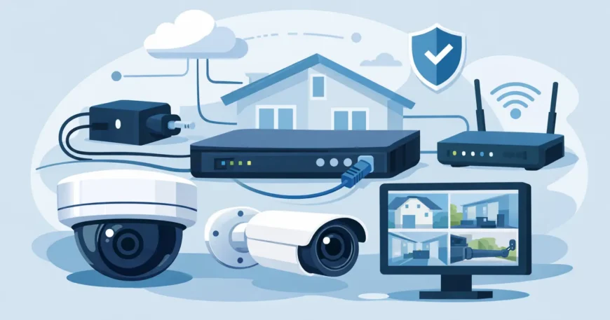
A camera is only as dependable as the cable, power and network behind it. Knowing how to wire a CCTV system properly helps avoid the common failures that matter most: cameras dropping out after dark, poor footage at the recorder, exposed cables, overloaded power supplies and a system that becomes difficult to expand.
For a home, small office, warehouse or multi-dwelling property, the goal is not simply to get pictures on a screen. It is to install a clean, serviceable surveillance system that records reliably and can be maintained without pulling walls apart later. The right method depends on whether you are installing IP cameras, analogue HD cameras, or a combination of both.
Start With a CCTV Wiring Plan
Walk the site before buying cable or mounting a camera. Identify the areas that need coverage, such as entrances, driveways, loading areas, reception, corridors, car parks, common areas and server rooms. Then decide where the recorder and network equipment will live. A secure, ventilated cupboard or communications rack is usually a better choice than leaving the recorder visible at a reception desk.
Every camera needs a route back to either a network switch, recorder, power supply or local junction point. Measure each cable route with enough allowance for vertical drops, service loops and routing around walls, ceilings and cable trays. Avoid planning a run solely by the straight-line distance. The actual pathway through a roof space, warehouse ceiling or riser can be substantially longer.
For commercial and strata-style properties, document every camera location, cable route and port number. Labelling may seem minor on installation day, but it saves time when a camera requires testing, replacement or relocation months later.
Choose the Right Cable for the Camera Type
The cable choice is determined by the CCTV platform. Using the wrong cable type or relying on temporary adapters can create faults that are hard to trace.
IP CCTV cameras
Most modern IP camera systems use Cat5e or Cat6 Ethernet cable. Cat6 is generally the better long-term choice for new work because it supports higher bandwidth, provides more headroom for network upgrades and suits professional structured cabling installations.
With Power over Ethernet, or PoE, one Ethernet cable carries both data and low-voltage power to the camera. This reduces the number of cables required at each location and removes the need for a separate power outlet near the camera. The cable runs from the camera back to a PoE switch or a PoE injector, then onwards to the network video recorder, known as an NVR, and the local network if remote access is required.
Standard Ethernet cable runs should generally stay within 100 metres from the switch to the camera. Longer distances may need a PoE extender, fibre link, additional network cabinet or a revised equipment layout. Do not assume a camera at the far end of a large warehouse will work reliably simply because an Ethernet plug clicks into place.
Analogue HD CCTV cameras
Analogue HD systems commonly use coaxial cable, often RG59, with BNC connectors for video. Many installations use a combined coax and power cable, sometimes called shotgun cable, so video and 12V DC power can be run together from the camera to the digital video recorder, or DVR.
Analogue cameras can be cost-effective where existing coax is already in place. However, cable quality, connector termination and voltage drop all affect image quality and reliability. Poor BNC connectors can cause interference, signal loss or intermittent footage that is easily mistaken for a faulty camera.
Wire IP CCTV Cameras With PoE
For most new installations, PoE IP cameras provide the cleanest wiring approach. The basic layout is camera to Cat6 cable to PoE switch to NVR or network. If the NVR includes built-in PoE ports, each camera can connect directly to one of those ports. Where cameras are spread across a larger site, a separate managed PoE switch is often more flexible.
Run solid-core, copper Ethernet cable through conduit, ceiling spaces, cable tray or approved low-voltage pathways. Avoid copper-clad aluminium cable. It is cheaper, but it is more prone to voltage loss, poor PoE performance and premature failure, particularly on longer runs.
Terminate each cable at the camera end and the cabinet end using the same recognised pinout, normally T568B. In a professional installation, it is often preferable to terminate fixed horizontal cabling onto a keystone jack or patch panel, then use short patch leads to connect cameras and switches. This protects the permanent cable and makes future fault-finding simpler.
Before mounting the camera permanently, test the cable with a cable tester and confirm that the switch detects the correct PoE load. Once the camera is online, check its image during daytime and at night. Infrared illumination draws additional power, so a camera that appears stable in daylight can still fail after dark if the PoE power budget is insufficient.
Plan Power Before You Install
PoE does not remove the need for power planning. It centralises it. Add up the maximum wattage of every camera, including PTZ cameras, infrared lighting, heaters and any other accessories. Compare this total against the PoE switch or NVR’s available power budget, not just the wattage listed for an individual port.
A switch may have eight PoE ports but only enough total power to operate six high-draw cameras reliably. Allow spare capacity for peak loads and later expansion. For a system protecting a business, warehouse or apartment common area, a small amount of capacity planning prevents costly downtime later.
For analogue systems, calculate voltage drop on every 12V DC run. Longer cable runs can leave a camera underpowered, causing dim infrared performance, flickering or complete dropouts. A centrally located, appropriately rated fused power supply is often cleaner than multiple plug packs, provided it is installed in a secure and accessible location.
Mains electrical work must be completed by a licensed electrician. CCTV, data and low-voltage cabling should also be kept separate from mains cabling and installed in accordance with applicable local requirements. Do not run camera cable loosely beside high-voltage wiring or use an unprotected lead as a permanent installation method.
Keep External Cable Runs Protected
Outdoor cameras need more than a weather-rated housing. Their wiring needs protection from UV exposure, moisture, physical damage and tampering. Use suitable conduit, weatherproof junction boxes and properly sealed cable entries. Leave a small drip loop below an outdoor cable entry so rainwater does not track along the cable into the camera or enclosure.
At each external camera, place joins inside an accessible weatherproof box rather than wrapping connectors in tape. Conceal cables where practical, especially at ground level or near accessible walls. A visible cable can be cut in seconds, defeating an otherwise well-positioned camera.
In areas prone to lightning or electrical surges, consider appropriate surge protection for outdoor network runs. This is particularly relevant for detached buildings, gate cameras and long runs between structures. Where buildings are separated, fibre may be a better backbone option because it is not electrically conductive and supports longer distances.
Set Up the Recorder and Network Correctly
The recorder should be located in a locked cabinet, communications room or other protected area. If someone can easily remove the NVR or DVR, they may take the evidence with them. Use a quality hard drive rated for surveillance recording, and size it according to the number of cameras, image resolution, recording schedule and retention period required.
For IP systems, assign clear camera names and maintain an address plan. Names such as “Warehouse Loading Dock North” or “Building B Level 2 Lift Lobby” are more useful than “Camera 07”. Confirm the NVR can see every camera, that timestamps are correct and that motion recording is detecting activity in the intended zones.
Remote viewing should be configured with strong unique passwords and current firmware. Avoid exposing devices directly to the internet where a secure manufacturer-approved remote access method or VPN is available. Remote access is convenient, but it should not become the weakest point in the system.
Test the System Like It Will Be Used
A final test should include more than confirming that each camera displays an image. Check every viewpoint at the time of day it will be relied on. Test faces at entry points, number plates where relevant, glare from windows, shadows in loading areas and infrared performance at night.
Review recorded footage rather than live video alone. Confirm that playback is smooth, motion events are being captured, recordings are retained for the required period and each camera is clearly identified. If the site has an internet outage or power interruption, know what will continue recording and what will need to restart.
A properly wired CCTV system is easier to trust because it is easier to support. Clean cable routes, labelled terminations, adequate power and thoughtful recorder placement turn surveillance from a collection of cameras into a dependable security tool that is ready when the footage matters.

